Spring Design
Design information for engineers, such as spring calculation formulas,
which are the basis of spring design, can be found here.
- Tokai Spring HOME
- Spring Design
- Volute Springs: Calculation Formulas
Volute
Springs
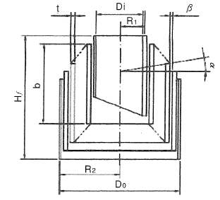
Meaning of Symbols
The symbols used for spring design are shown in Table 1 below. The values of the transverse elastic modulus (G) are based on Table 2.
Table 1. Symbols and units used in calculations
| Symbol | Meaning of Symbol | Unit |
|---|---|---|
| P | Load applied to the spring | N |
| δ | Spring deflection | mm |
| Hf | Free height | mm |
| Na | Number of active coils | — |
| R1 | Radius of the smallest active coil | mm |
| R2 | Radius of The largest active coil | mm |
| G | Transverse elastic modulus | N/mm2 |
Table 2.Transverse elastic modulus:G(N/m㎡)
| Material | G Value | |
|---|---|---|
| Spring steel material | 7.85×10⁴ | |
| Stainless Steel |
SUS304(Correspond to X5CrNi18-9,1.4301,S30400) SUS316(Correspond to X5CrNiMo17-12-2,1.4401,S31600) SUS631J1 |
6.85×10⁴ 6.85×10⁴ 7.35×10⁴ |
| Phosphor bronze wire | 4.2×10⁴ | |
| Beryllium copper wire | 4.4×10⁴ | |

Basic Calculation Formula Used for Design
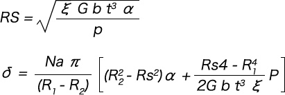
To calculate the spring constant up to the point where the horizontal spacing between adjacent plates becomes 0 between the plates during compression, the basic formula below can be used.

To calculate the spring characteristics between the plates after being compressed to the point where the horizontal spacing between adjacent plates becomes 0, the basic formula below can be used.


