Spring Design
Design information for engineers, such as spring calculation formulas,
which are the basis of spring design, can be found here.
- Tokai Spring HOME
- Spring Design
- Extension Springs: Calculation Formulas
Extension
Springs
Meaning of Symbols
The symbols used for extension spring design are shown in Table 1 below. The values of the transverse elastic modulus (G) are based on Table 2.
Table 1. Symbols and units used in calculations
| Symbol | Meaning of Symbol | Unit |
|---|---|---|
| d | Material diameter | mm |
| D | Coil center diameter | mm |
| Hf | Free length | mm |
| Na | Number of active coils | — |
| P | Load applied to the spring | N |
| δ | Spring deflection | mm |
| k | Spring constant | N/mm |
| Pi | Initial tension | |
| τi | Initial stress | mm |
| M | Torsion moment, bending moment | N/mm |
| σ | Tensile stress | N/mm2 |
| τ0 | Uncorrected shear stress | N/mm2 |
| τ | Corrected shear stress | N/mm2 |
| κ | Stress correction factor | — |
| c | Spring index | — |
| G | Transverse elastic modulus | N/mm2 |
Table 2. Transverse elastic modulus: G(N/m㎡)
| Material | G Value | |
|---|---|---|
| Spring steel material Hard steel wire Piano wire Oil-tempered wire |
7.85×10⁴ | |
| Stainless steel | SUS304(Correspond to X5CrNi18-9,1.4301,S30400)
SUS316(Correspond to X5CrNiMo17-12-2,1.4401,S31600) SUS631J1 |
6.85×10⁴ 6.85×10⁴ 7.35×10⁴ |
| Brass wire | 3.9×10⁴ | |
| Nikel-silver wire | 3.9×10⁴ | |
| Phosphor bronze wire | 4.2×10⁴ | |
| Beryllium copper wire | 4.4×10⁴ | |
Deflection and Stress of the Coil Part of Extension Springs
The basic formula for the deflection of the coil part is calculated using the formula of the compression coil spring

However, to calculate the load, it is necessary to consider the initial tension. If this initial tension is Pi, any load (P) will be

From formula (1), the deflection (δ) is as per the following formula.

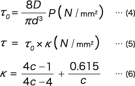
The shear stress τ0・τ are calculated with the following formulas just like with the compression coil spring.

Stress of the Hook Part of Extension Springs
As the tensile stress and the shear stress based on the bending moment and the torsion moment are generated from the hook part, it is complicated to reach an accurate calculation. Here, we introduce approximate calculations for the widely used machine half hooks and U-shaped hooks.
(i)In the Case of a Machine Half Hook
In Figure 1, the maximum tensile stress value occurs inside part A, and the maximum shear stress value occurs inside part B.
As the maximum tensile stress inside part A is the sum of the bending moment (M) and the tensile stress according to the axial load (P), it becomes

Here, K1 is the stress concentration coefficient based on the curvature, and if
 , it can be found with the following formula.

When formula (7) is rearranged, we get the following formula.

K1, however, is as follows.

Here, C is the spring index of the coil part.
The maximum shear stress at the inside of part B is due to the torsion moment M.

Here, K2 is the stress concentration coefficient based on the curvature, and if
 , it can be found with the following formula.

(ii)In the Case of an U-shaped Hook
In Figure 2, the maximum tensile stress value occurs inside part A, and the maximum shear stress value occurs inside part B.
As the maximum tensile stress inside part A is the sum of the bending moment (M) and the tensile stress according to the axial load (P), it becomes

Here, K3 is the stress concentration coefficient based on the curvature, and if
 , it can be found with the following formula.

When formula (13) is rearranged, we get the following formula.

K’3, however, is as follows.

The maximum shear stress at part B is given with formula (11) just like in the case of the machine half hook. Hooks of other shapes may also be considered in the same way.


