Spring Design
Design information for engineers, such as spring calculation formulas,
which are the basis of spring design, can be found here.
- Tokai Spring HOME
- Spring Design
- Conical Springs: Calculation Formulas
Conical
Springs
Meaning of Symbols
The symbols used for spring design are shown in Table 1 below. The values of the transverse elastic modulus (G) are based on Table 2.
Table 1. Symbols and units used in calculations
| Symbol | Meaning of Symbol | Unit |
|---|---|---|
| P | Load | N |
| δ | Spring deflection | mm |
| δ1 | Deflection of the free coils | mm |
| δ2 | Deflection of the solid coils | mm |
| R | Coil average radius at angle θ | mm |
| R1 | Minimum coil average radius | mm |
| R2 | Maximum coil average radius | mm |
| θ | Spindle rotation angle from the point of radius R2 to the point of length s along the coil | |
| n | Initial number of coils | — |
| n’(=θ/2π) | Number of coils from R2 to the angle θ | — |
| n1 | Number of free active coils | — |
| n2 | Number of solid active coils | — |
| d | Wire diameter | mm |
| Ip(=πd4/32) | Second moment of area | mm4 |
| φ=PR/GIp | Torsion angle per unit length of wire | rad(°) |
| ν=( R2-R1)/n | Change in coil average radius per coil |
Table 2. Transverse elastic modulus: G(N/m㎡)
| Material | G Value | |
|---|---|---|
|
Spring steel material Hard steel wire Piano wire Oil-tempered wire |
7.85×10⁴ | |
| Stainless steel |
SUS304(Correspond to X5CrNi18-9,1.4301,S30400) SUS316(Correspond to X5CrNiMo17-12-2,1.4401,S31600) SUS631J1 |
6.85×10⁴ 6.85×10⁴ 7.35×10⁴ |
| Brass wire | 3.9×10⁴ | |
| Nickel-silver wire | 3.9×10⁴ | |
| Phosphor bronze wire | 4.2×10⁴ | |
| Beryllium copper wire | 4.4×10⁴ | |
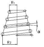
In a conical coil spring with a fixed pitch angle, R and n’ (= θ / 2π) are associated with the following formula.

Therefore, the height (H) to the n(th) coil measured from the maximum coil diameter under no load can be expressed by the following formula when the pitch angle (α) is small.

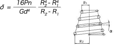
The deflection before the coils are compressed to the ground is calculated by integrating dδ = (2πφ / ν) R2dR, where ds is eliminated from the two formulas dδ = Rφds and dR = (ν / 2πR) ds, from R1 up to R2.

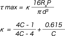
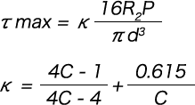
As the maximum shear stress occurs at the point of the maximum coil radius (R2), the following formula is obtained.

However, from the formula with κ expressed as c = 2R2/d,

Deflection and stress after the coils are compressed to the ground are calculated as follows.
The coil expansion curve when the cylindrical coil spring is at its solid height is a straight line, but for the conical spring, it has somewhat of a curve.
However, the expansion curve of the solid part with θ on the horizontal axis can be expressed by a straight line h = θd’ / 2π.
Therefore, the angle of inclination (α’) of the expansion curve of the actual solid part is as per the following formula.

However, d’ is the centre-to-centre distance of the solid coils shown in Figure 1 and is calculated from the following formula.

Therefore, if the pitch angle (α) is not too large, the following formula will hold true.

If this is integrated from 0 to 2n2π with respect to θ, we get the following formula.

Here, the relationship of n2/n = (R2 – Rs) / (R2 – R1) is used.
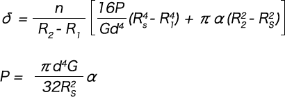
As δ1 is calculated as Rs instead of the numerator R2 in formula (1-1), the deflection (δ) is as per the formula below.

Formula (1-2)
Meanwhile, there is a relationship in which the load (P) becomes Rs.

This can, therefore, be rewritten as follows.

Formula (1-3)
In such a case, the coils are compressed not to the adjacent coils but to the support surface.
The deflection and load in this case can be expressed by the following formula by setting d’ = 0 in formulas(1-2) and (1-3).
The maximum shear stress (τ max) is calculated with the following formula, regardless of whether the coils are compressed to the adjacent coils or the support surface.

κ can be calculated from the following formula with c = 2Rs / d.

Summary of Conical Spring Calculation Formulas (when pitch angle is fixed)
(1) Deflection when the coils start to compress to the ground
(2) Stress when the coils start to compress to the ground
(3) Deflection after when the coils start to compress to the ground

○When the coils are compressed to the support surface instead of being compressed to each other (1 – (R2 – R1) / nd ≤ 0)

(4) Load after when the coils start to compress to the ground
○When coils are compressed to each other (1 – (R2 – R1) / nd > 0)

○When the coils are compressed to the support surface instead of being compressed to each other (1-(R2-R1)/nd≦0)

(5) Stress after when the coils start to compress to the ground
