Spring Design
Design information for engineers, such as spring calculation formulas,
which are the basis of spring design, can be found here.
- Tokai Spring HOME
- Spring Design
- Torsion Springs: Things To Note In Spring Design
Torsion
Springs
(1)Shape of the End Part
The shapes of springs are very complex because various shapes are required depending on how the spring is mounted and where it is mounted.
We do, however, recommend that the arm shape of the end parts be made as simple as possible and that the bending radius be larger than the diameter (d) of the material.
Consideration needs to be taken when designing the spring as it will affect the spring’s service life.

(2) Impact of the Arm Length
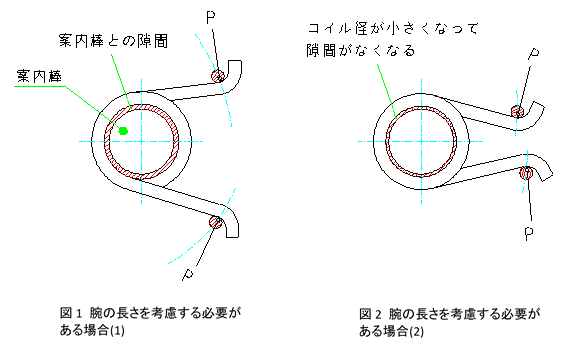
If the arm is long, ir should be considered as a cantilever with length a.


(3)Impact of Direction of the Moment
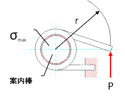
The maximum tensile stress position and value differ depending on the direction of the moment (winding direction or unwinding direction). When wound, the maximum tensile stress is on the outside of the coil, and there are no problems with the aforementioned formula.
However, when rewound, the maximum tensile stress shall occur inside the coil. In this case, the stress correction coefficient (κ) is used.


Figure 3. Acting in the unwinding direction
(4)Selection of the Guide Stud
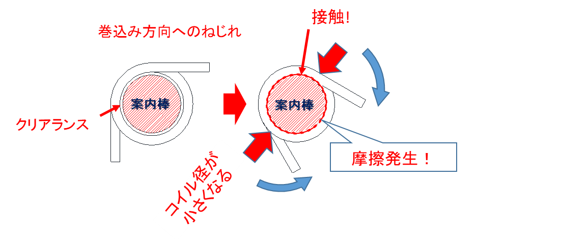
When used in the direction in which the spring is wound, the coil diameter will decrease. Therefore, when using a guide stud, it is necessary to estimate this amount in advance. We recommend setting the guide stud diameter (Ds) to 90% of the maximum coil inner diameter.


Figure 4. Reduction in coil diameter when acting in the winding direction
(5)Others
When used, the springs often deform in the radial direction of the coil regardless of whether the moment is equal or not.
This deformation increases when the number of coils is 3 or less.
The deformation varies depending on the shape of the arm, how the spring is mounted, and the mounting angle. In this case, please note that there may be instances that do not fit the basic design formula.


